
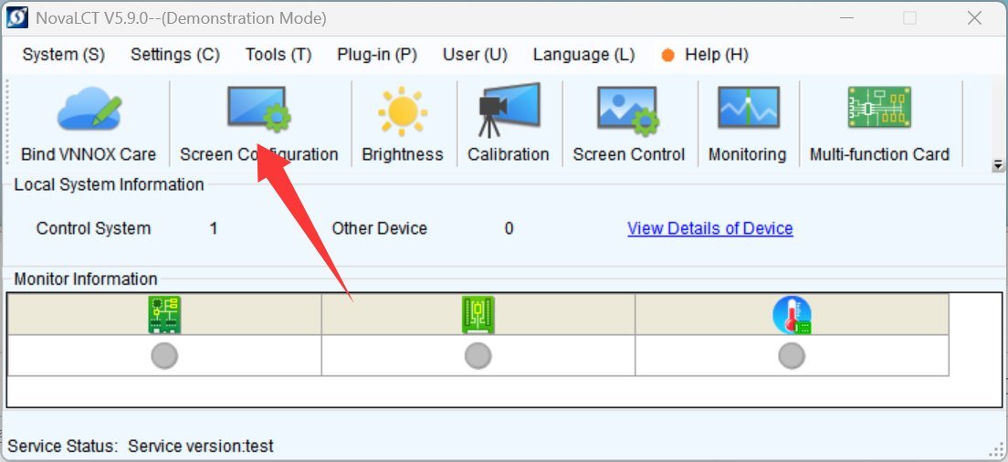
When half of an LED screen is blank, the cause is not always damaged hardware. The port mapping may not match the physical network cables, the cabinet cascade may be reversed, the software direction may differ from the cabinet direction, an output branch may be overloaded, or a signal route may be open. In NovaLCT, the objective is not simply to fill in numbers. The logical route in the software must match the physical route at the site.
Before configuring, draw the cabinet numbers from the real viewing direction: left to right, top to bottom or the approved custom path. Mark cabinet power input, signal IN, signal OUT, receiver address, maintenance direction and zone. Then place the sending-device port, optical-converter port and screen zone in the same table. Take photos that show the port label, arrow and cabinet number together when possible.
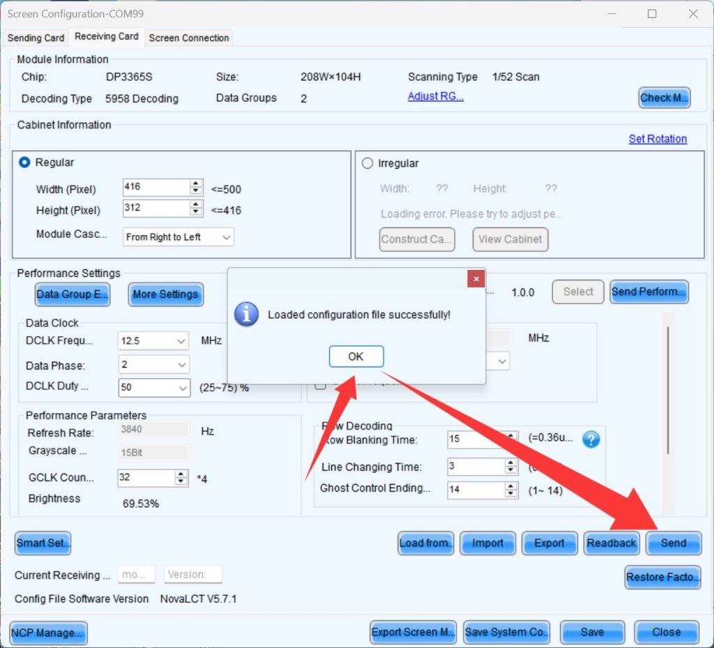
When creating the screen configuration, confirm total pixels, cabinet rows and columns, cabinet resolution, cascade order and output ports. Map each port to the actual cabinet path. If the physical screen is irregular, split into zones or contains gaps, do not automatically draw a large rectangle and expect the empty areas to behave correctly. Use the physical-cabinet layout or a non-rectangular loading method supported by the current equipment, and confirm that the processor actually supports it.
Loading must be reviewed at two levels. First, confirm that the total screen pixels are within the processor/sending-device capacity. Second, confirm that the pixel load and physical branch length for each output port are within the model’s limits. Official specifications are model-specific; a port number or loading figure from one controller must not be applied to another. Even when the total pixel count is acceptable, a long cascade, poor link or mismatched cabinet configuration can still create a local blank area.
Before sending, save the existing configuration. Use a low-risk test sequence: connect one known-good cabinet, confirm direction and image, add the next cabinet on the same branch, and then expand to the full zone. Record each step. If the fault starts when one cabinet is added, inspect that cabinet’s upstream/downstream cable, receiver address, cascade direction and configuration instead of rebuilding the whole display immediately.
Use a grid, arrows, cabinet numbers, solid colours and black field for validation. The grid finds misalignment, arrows confirm direction, numbers verify mapping, solid colours reveal channel behaviour and black shows unwanted light. For three independent screens, test each zone separately. A complete preview in the software does not prove that the physical mapping is correct.
When a port is changed, update both the software map and the physical label. Do not leave a cable in a new port while the drawing still shows the old port. If a temporary test uses a short chain, write “test only” on the diagram and restore the approved route after the test. A future installer should be able to reproduce the test without guessing which cabinet was used.
Loading should also be reviewed for the actual content mode. High frame rate, high bit depth, low latency or special processing modes can impose limits different from ordinary playback. The current official controller specification and operating mode should be the reference. If the customer is using three independent screens, calculate the total and each zone separately; the fact that a processor has enough total capacity does not mean every output port has the same capacity or that the chosen layout is valid.
Keep a port-mapping checklist with four photographs: sending device, first cabinet, a mid-chain cabinet and the final cabinet. Add the direction arrows and zone names. This evidence is especially useful when a customer reports that the lower half or right-hand branch is blank after a cabinet has been moved. It lets support compare the original topology with the current one before asking the site to change anything.

Frequently Asked Questions
Q1: How many cabinets can one port carry?
There is no safe universal number. Check the exact sending/receiving devices, cabinet resolution, pitch, branch topology and official loading table.
Q2: Why does the software preview look complete while the real screen is half blank?
Port mapping, cascade direction, physical links, receiver addresses or configuration may not match the site.
Q3: Can an irregular screen be configured as a large rectangle?
Only when the controller and software support the layout and the empty coordinates and loading have been verified.
Q4: What is the most important action before sending a new configuration?
Back up the current file, label cabinets and ports, confirm the correct screen zone and test one known-good cabinet first.
